
One of charts that give you a quick overview of what’s happening in a project or product work is Cumulative Flow Diagram (CFD). On one hand in CFD you can find typical information about status of work: how much work is done, ongoing and in backlog, what is the pace of progress, etc. This is the basic stuff. On the other hand, once you understand the chart, it will help you to spot all sorts of issues that a team may be facing. This is where Cumulative Flow Diagram shows its real value.
Before we move to all the specific cases let me start with the basic stuff though (feel free to scroll down if you’re familiar with this part).

The mechanism of Cumulative Flow Diagram is very simple. On a vertical axis we have a number of tasks. On a horizontal one we have a timeline. The curves are basically a number of items in any possible state shown in a time perspective. The whole trick is that they are shown cumulatively.
If the green curve shows stuff that is done it will naturally grow over time – that’s simple. If the blue line shows tasks that are in progress, and we have stable amount of work in progress it will still go up as it adds to the green line. In other words work in progress would be represented by the gap between the blue and the green lines… We’ll come back to that in a while.
Any line on CFD represents a specific stage. In the simplest example we’d have items that are to be done, stuff that is ongoing and things that are done.
For the sake of the rest of this article I’m going to use a simple process as a reference.

We have a backlog, items that are in development or testing and stuff that is done. For the sake of Cumulative Flow Diagram examples it doesn’t matter whether tasks in development are ongoing or done and waiting for testing. However, as we will find later, there may be some indicators that would make tracking these two stages separately valuable.
With such a workflow our Cumulative Flow Diagram may look like this.
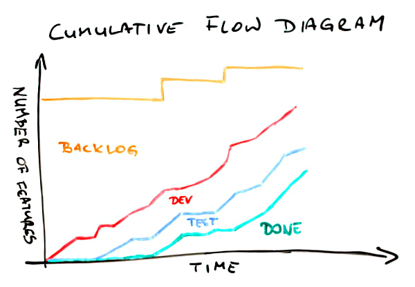
First, the meaning of the lines. The green one shows how many items have been delivered over time. Everything that is between the blue and the green curves is stuff that is in testing. The area between the red and the blue lines shows how much stuff is in development (either ongoing or done). Finally, the top part below the orange line is the backlog – how many items weren’t yet started.
In a glimpse we can find a few important bits of information about this project. First, after slow start a pace of delivery is rather stable. Pretty much the same can be said about work that is in progress – the pace is stable and things go rather smoothly. We know that the scope has increased a couple of times, which we can tell looking at jumps of the orange line. Finally, comparing where the green line (done) and the orange line (scope) are on a vertical axis right now we can say that we’re not yet halfway through the project.
Quite a lot of information for the few seconds, isn’t it? Well, there is more.

On this CFD a few things have been shown explicitly. One is a scope change. We’ve discussed it on the previous chart too. Another one is the space between the red and the green lines. It represents work in progress (WIP). Note, basing on Cumulative Flow Diagram only you can’t learn how much work in progress you have precisely; it is some sort of approximation. Pretty good one, but only approximation. It is a very good indicator how WIP is changing over time though. There also is an arrow labeled “prod. lead time” where “prod.” stands for production. It roughly shows how much time we need to complete an item. Again, it shouldn’t be used as the ultimate lead time indicator but it shows pretty well what lead time we’ve had and how it changes over time. Finally, we can approximate slope of done curve to roughly estimate the delivery time. Of course if the scope changes the delivery time will change as well thus the scope line (the orange one) is also approximated.
Now, we have even more information. Yay!
You will rarely see such nice Cumulative Flow Diagrams though. And that’s good news actually. I mean if CFD looks plain and nice all the time you can only learn that much from it. The real CFD magic is revealed when things don’t go so well.
Let’s go through several typical cases.

In this situation the spread between the red and the green lines is growing over time. It indicates a really bad thing – we have more and more work in progress. That sucks. Increased WIP means increased lead time as well. Not only is time to market longer but also it is more and more difficult to deliver anything fast when we need it.
That’s not the worst thing. The worst thing is that with increased amount of work in progress we also increase multitasking thus we incur all the costs of context switching making the team less efficient.
Do we know that for sure? Um… no, not really. I make here an assumption that the team setup hasn’t changed, meaning that we have the same people spending similar amount of time on a project, etc. If it was Cumulative Flow Diagram for a team that is constantly growing and then it would be just OK. The chart may also present an increasing number of blocked tickets which definitely would be a problem but a different one then described above.
In either case such a situation is a call for more analysis before jumping to conclusions. The potential reasons I offer you with this and following charts are simply the likely ones; not the only available.
By the way, please treat all the following remarks keeping that in mind.
One more interesting observation about this Cumulative Flow Diagram is that we have no clues where the root cause for increasing WIP lays. Neither development nor testing part seems to be steadily attached to any other line over time. A further investigation is a must.
There are charts where we get some clues which stage of a process is problematic.

Whoa, this time the development part compared to the testing part is really heavy. What can we learn from it? We don’t have problems with testing. Also, if a definition of testing is “testing and bug fixing,” which is a typical approach, it doesn’t seem that quality of work is much of an issue either. If we are to point fingers we’d point them to development part, wouldn’t we?
And we might have been wrong. Of course one thing that may be happening here is a lot of items in development but few of them ready to test. Another issue though may be that there is a lot of stuff waiting for testing but availability of testers is very limited and when they’re available they focus on finishing what they started.
How can we tell? We can’t unless we have more data. In fact, another line on the chart – one that distinguishes items in “development ongoing” from those in “development done” – would help. Without that the CFD is only an indicator of a problem and a call for a deeper analysis. After all, that’s what Cumulative Flow Diagrams are for.
Another flavor of a similar issue is on the next CFD.

We can find two things here. Let’s start with the more obvious one – the shape of the green line. It looks like stairs, doesn’t it? Stairs are typical when the last stage, which commonly is some sort of deployment, is done in cadences, e.g. weekly, biweekly, etc. Building on that, a stairs-shaped delivery line mean that work in progress and lead time would vary depending on a moment of release cadence you’re in. Maybe it’s time to make a step toward continuous
There is one more thing here though. There is pretty significant, and increasing, number of items that are in testing but don’t get released. The gap between the blue and the green line is growing with each consecutive release.
This one is a real issue here. It may mean that we have a problem with quality and we can hardly reach a state when an item has all the bugs fixed. It may mean that developers simply don’t pay much attention to fixing bugs but tend to start new stuff; at the same testers would follow up on new stories as they wait for bug fixes for the old ones anyway. It may mean that a code base is organized in a way that doesn’t allow releasing everything that is ready. Once again, the root cause is yet to be nailed but at least we know where to start.
It seems we have more questions than answers. If you think that I’m not helping it will be no different with the next example.

This would happen occasionally in almost every team. All the lines flatten out. What the heck? The first thing I do when I see that is I check for public holidays or company-wide event happening during that time. It may simply be time when no one was actually working on a project and there is a perfect explanation for that.
Sometimes it is not the case though. This is when things get interesting. If everyone was at work but the chart still indicates that no one got anything done it most likely tells a story about serious problems. A staging environment could have gone down so everyone has been focusing on bringing it back alive. Another project could have needed help and virtually everyone has been sucked there. There could have been a painful blocker that has forced everyone in the team to refocus for a while.
In either case, whatever it was it seems to be solved already as the team is back on track with their pace.
Another flavor of such a scenario would look a bit differently. It would give more hints too.

There are two important differences between this and the previous Cumulative Flow Diagrams. One is that, in this case, only two lines flatten out; the development line keeps the healthy progress. The other is that ends of both the green and the blue line are as flat as a table top.
The latter suggests that whatever is the problem it isn’t solved yet. What the problem might be though? It seems that the team has no problem starting development of new items. They can’t, however, start testing, thus they clearly can’t deliver anything either. One of probable hypothesis would be that there is something seriously wrong with either the testing environment or the testers.
In the first case it just isn’t technically possible to verify that anything works as intended. In the second it seems something bad happen to our only tester (if there were more than one there would likely be some progress). There is another hint too. Developers don’t seem to care. They just start, and possibly complete, their stuff as if nothing happened.
I’d say that these guys have to deal first with the issue and then discuss how they collaborate. I sense a deeper problem here.
The same way as the previous example indicates an issue in the way people cooperate, the next one suggest a quality problem.

Development line goes up in a stable and predictable manner. The testing curve? Not so much. And we better not mention the done line. Obviously we have more and more work in progress here over time – we’ve covered this one before.
But wait, then suddenly the magic happens and everything goes back on track. At the very end we have decently small amount of work in progress and much stuff delivered. The smell here is how the done (and testing to some point as well) curve skyrockets at the end.
How come that earlier such pace was impossible? I’d challenge the idea that the team suddenly become so fast. Of course they might have not kept the board up-to-date and then, out of the blue, have realized that they’ve had way more finished items that they’ve thought they had.
More likely scenario is that under pressure they just deployed whatever seemed at least remotely close to working. If that’s true the problem isn’t solved at all and it’s going to come back to bite them in their butt. A curious reader may try to draw a picture how further part of Cumulative Flow Diagram would look like in this case.
The next one is one of my favorites. I wonder why it is so far down the list. Oh well…

This Cumulative Flow Diagram is surprisingly common. Let’s try to list a few things that we can find here. The development curve goes up aggressively. Halfway through more than 80% of items are started. Testing doesn’t go nearly that well. And delivery? Well, the start was crappy, I admit, but then it simply went through the roof. And it isn’t only a single day that would suggest delivery of uncompleted stuff. Odds are that these items are properly done. Wouldn’t bet the real money on that but wouldn’t be surprised if that it was so either.
Of course we have very high WIP in the middle of this CFD but at both ends the gap seems to be significantly smaller.
Ah, one more thing. It seems that at the end of the day we’ve delivered everything that was in the backlog. Yay!
Now, what would be the diagnosis in this case? Time boxing! This is one of classic visualizations of what typically happens over the course of an iteration. If a team is comfortable with planning and has rather stable velocity it’s likely that they’d fill backlog with reasonable amount of new features.
Then, given no WIP limits within the time box everyone does their own thing: developers quickly start many features having no pressure other than the end of the iteration to finish stuff. Eventually, the backlog is cleared so the team refocuses to finish stuff, thus the acceleration at the latter stages of the process.
If you pictured a series of such Cumulative Flow Diagrams attached one to another you’d see a nice chain going North-East. You’d find many of these in Scrum teams.
Another chart, despite some similarities to the previous two, suggests a different issue.

In this case almost everything looks fine. Almost, as the done line barely moves above the horizontal axis. However, when it finally moves it goes really high though. What does it mean?
My guess would be that the team might have been ready with the stuff but, for whatever reasons, they wouldn’t deliver. In fact this is one of typical patterns in fixed price, fixed date projects, especially in bigger ones. Sometimes a basic measure that is tracked is how many items are done by the production team. No one pays attention whether it can possibly be deployed in production or even staging environment.
Eventually, it all gets deployed. Somehow. The deployment part is long, painful and frustrating though. Cumulative Flow Diagram representation of that pain and tears would be that huge narrow step of the done curve.
Talking about huge and narrow steps…

Another chart has such a step too. We’ve already covered its meaning at the very beginning – it is the change of the scope. In this case it is not about the fact that such change has happened but about its scale and timing.
First, the change is huge. It seems to be more than a half of initial scope added on the top of it. Second, it happens out of the sudden and pretty late in the project. We might have been planning the end date and now, surprise, surprise, we barely are halfway through again.
Now, this doesn’t have to be a dysfunction. If you were talking with the client about the change or it is simply a representation of expected backlog replenishment that’s perfectly fine. In either case you it shouldn’t come as a surprise.
If it does, well, that’s a different story. First, if you happen to work on fixed prices contract… man, you’re screwed up big time. It isn’t even scope creep. Your scope has just got on steroids and beaten world record in sprint. That hurts. Second, no matter the case you likely planned something for these people. The problem is it’s not going to happen as they have hell lot of work to do in the old project, sorry.
So far lines on Cumulative Flow Diagrams were going only up or, at worst, were flat. After all, you’d expect that given the mechanism of creating the chart. That’s the theory. In reality a following chart shouldn’t be that much of a surprise for you.

Whoa! What happened here? A number of stories in testing went down. The red line representing stuff in development followed but don’t be fooled. Since the gap between the red and the blue line is stable nothing really happened to the items in development; it’s only stuff in testing that was affected.
Now, where did it go? Definitely not to done bucket – the green line didn’t move. It didn’t disappear either as the total number of items (the orange line) seems to be stable. A few items had to go from testing to backlog then.
What could it mean? Without an investigation it’s hard to say. I have good news though. The investigation shouldn’t be long – such things don’t happen every other day. For whatever reasons stuff that was supposed to go past code complete milestone was marked as not started.
I sense a major architectural or functional change. What’s more, it’s quite probable that the change was triggered by the tests of aforementioned items. Unfortunately it also means that we’ve wasted quite some time building wrong stuff.
Another flavor of that problem looks a bit scarier.

Again, the total scope didn’t change. On the other end every other line took a nosedive. Once again amount of stuff in development doesn’t seem to be affected. This time the same can be said about items in testing. It’s the delivered stuff that got back to the square one.
It means that something that we though was done wasn’t so. One thing is that we were building wrong stuff, exactly as in the previous example, only we discovered it later. We likely pay the order of magnitude bigger price for the late discovery.
There’s more in it though. This Cumulative Flow Diagram shows that we likely have problems with acceptance criteria and / or collaboration with a client. I mean how come that something that was good is not so anymore? Either someone accepted that without checking or we simply don’t talk to each other. No matter the case it sucks big time.
Would the orange line never move down then? Oh yes, it would.

I mean, besides an obvious case where a few items are removed from backlog and the only line that moves down would be the orange one, we may find this case. Using the technique perfected in the previous examples we will quickly find that a few items that were in testing are… um, where they are actually?
Nowhere. They’ve disappeared. They haven’t been completed, they haven’t been moved back. These items are no more.
What does it mean? First, one more time we’ve been working on wrong stuff (fools we are). Second, we’ve figured it out pretty late (but could have been later). Third, the stuff doesn’t seem to be useful at all anymore.
It’s likely that we realized that we don’t know how exactly build this or that and we asked the client just to learn that they don’t need either of those anymore. It’s also likely that we’ve encountered a major technical issue and rethought how we tackle the scope possibly simplifying the whole approach. Whatever it was, if we had figured it out earlier it wouldn’t have been so costly.
Finally, one more Cumulative Flow Diagram I want to share with you.

Think for a while what’s wrong with this one.
When compared to the previous charts it seems pretty fine. However, by now you should be able to say something about this one too.
OK, I won’t keep you in suspense. In the first part of this CFD work in progress was slowly but stably growing. However, it seems that someone noticed that and the team stopped starting new stuff. You can tell that seeing how relatively flat the red line has become somewhere in the middle of the chart.
Given some time testing and delivery, even though their pace hasn’t changed, caught up. Work in progress is kept at bay again and the team’s efficiency is likely improved.
As you can see, despite past several examples, you can see the effects on improvements at Cumulative Flow Diagrams too. It’s just that CFD is more interesting in terms of learning that you have a problem than finding confirmation that you’ve solved it. The latter will likely be pretty obvious anyway.
Congratulations! You made it through to what is probably the longest article in the history of this blog. Hopefully you now understand how to read Cumulative Flow Diagrams and what it may indicate.
I have bad news for you though. You will rarely, if ever, see such nice CFDs as shown in the examples. Most likely you will see an overlapping combination of at least a few patterns. This will likely make all the lines look like they were tracing a rollercoaster wagon.
Fear not. Once you get what may be happening under the hood of the chart you will quickly come up with the good ideas and the right places to start you investigation. After all, Cumulative Flow Diagram will only suggest you a problem. Tracking it down and finding an antidote is a completely different story.
However, if you’re looking for a nice health-o-meter for your team Cumulative Flow Diagram is a natural choice.


